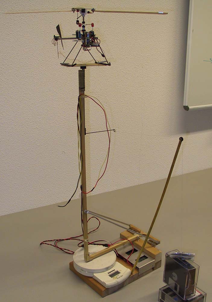
The complete testbench, the second scale for torque measurement should be in place of the floppy boxes.
Here a few pictures of the testbench.
It is build using two scales, only one is shown on the pictures.
Using the stand I can measure thrust, rotor torque, current, voltage, and RPM.
If you know the motor data, these data enable calculation of the motor efficiency, gear efficiency,
average rotor lift coeffcient and average rotor drag coefficient. This is a real help for the development of new blades.
On the stand the motor is fed from a laboratory power supply, in this way the rotor RPM can be changed easily.
Voltage is measured quite near to the motor terminals to reduce measurement errors. Current is measured using a 0.01 ohm shunt.
With standing rotor both scales are tarred, the measurments will then be shown in negative numbers.
The spring action of the power leads itroduces a small error in the torque measurement. To reduce this error use an electronic scale (short travel)
and a stiff CF platform shaft.
The complete testbench, the second scale for torque measurement should be in
place of the floppy boxes.
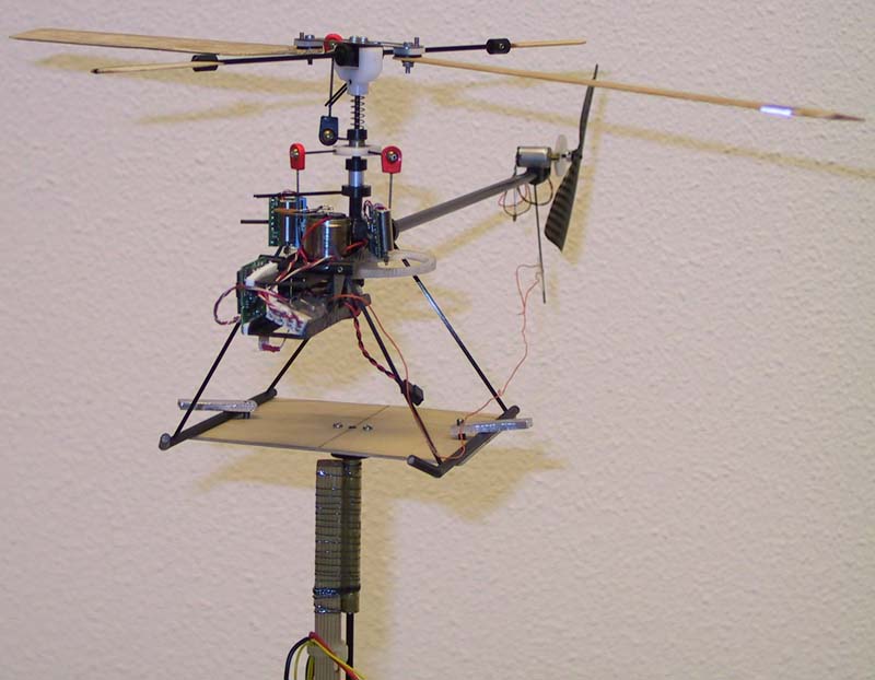
Micro heli mounted on a ball beared rotating platform.
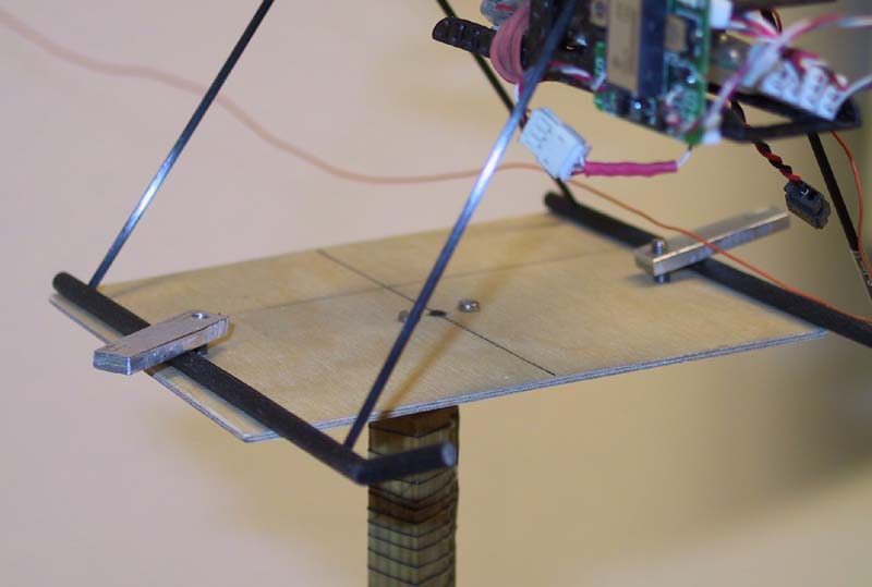
Mounting point for the heli.
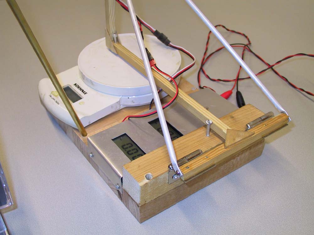
Frame hinged to baseplate containing meters for current and voltage.
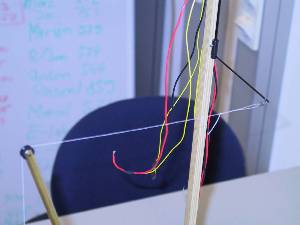
A piece of thin tread connects an arm on the rotating platform
to a weight on the second scale for torque measurement.
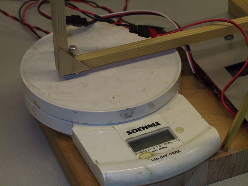
An adjustment screw to level the hinged frame. In the back you see the connectors for voltage and current measurement.
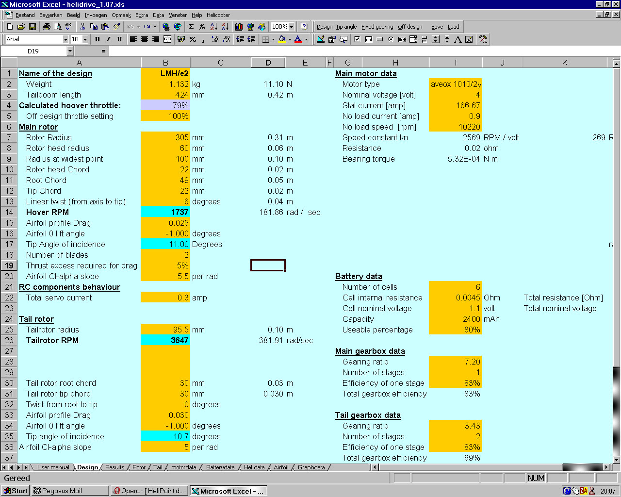
For the development of this heli a wrote a piece of software in Excel. Herewith I can calculate the performance of the heli and make good choices
for weight, rotor size, motor and gearing. If you are interested drop me a line.
Here is a screenshot of one of the pages of the program:
Back to home